Experiment set ELECTRICS 5 ADDESTATION MGA

Data logging and sensors
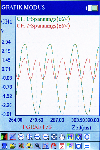
For demonstrative experiments on electromagnetic induction, transformer processes, rectification of AC voltage or the switch-on procedure for a coil, you need a dual-channel oscilloscope. That is the only way that opposing phases for primary and induced voltages can be displayed convincingly. Until now, though, it has not been possible to provide enough sets containing such equipment for all the students in a class simply for reasons of cost.
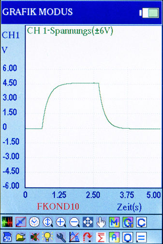
However the oscilloscope for the ELECTRICITY 5 ADDESTATION set is generated by the MGA software and can display up to four different parameters simultaneously. This is particularly helpful for half-wave and full-wave rectification, but also for transformers, since the relevant curves and phase shifts can be investigated highly accurately with colour coding. In addition, measurements can also be displayed in digital form or in a vector diagram. The digital method is especially good for deriving Ohm’s law. The measurements can automatically be transferred to a table or plotted in a graph. By touching the relevant function buttons, you can see not only a graph but also the equation for the resulting straight line.
Visualisation of readings
Die Messwerte sind auch digital oder im Zeigerdiagramm darstellbar. Die digitale Methode eignet sich besonders für die Erarbeitung des Ohmschen Gesetzes. Hier können die Messwerte automatisch in eine Tabelle sowie in ein Koordinatensystem übertragen werden. Durch Antippen der betreffenden Funktionsfelder erscheinen dann sowohl Graph wie auch Gleichung der zugehörigen Gerade.
01.01.10 Storage case
14.02.50 Inlay with cut-outs for E5
14.03.50 Base plate E5
08.05.00 Coupling E7 (2 pieces)
14.05.50 Switching element
23.05.00 Sensor connection cable (2 pieces)
14.06.50 Bulb element E5
23.06.00 Current sensor
08.07.50 Switch element
23.07.00 Voltage sensor (2 pieces)
08.08.50 Potentiometer element
14.08.00 End plate E5 (2 pieces)
16.08.00 Acrylic glass tube with scale A1
06.09.00 Round rod magnet AlNiCo (2 pieces)
14.09.50 Transistor element E5
03.10.01 Screw spring 10 N/m
14.10.00 Test tube with hook
14.11.50 Resistance element R1
14.12.50 Resistance element R2
14.13.50 Resistance element R3
14.14.50 Resistance element R4
08.16.30 Si-diode element
14.16.30 Capacitor element 4.7 μF
14.16.50 Capacitor element 10 μF
14.16.70 Capacitor element 47 μF
07.17.00 Coil with 300/600 turns
08.18.00 Experiment cable 8.5 cm (2 pieces)
08.19.00 Experiment cable 17 cm (2 pieces)
08.20 00 Experiment cable 34 cm blue (2 pieces)
14.22.00 Adjusting plate
14.23.50 Bridge rectifier circuit element
06.24.20 Experiment cable 25 cm blue (3 pieces)
08.24.50 Resistance element 1 kΩ
08.26.50 Resistance element 10 kΩ
14.24.50 Resistance element 22 kΩ
08.27.00 Shorting link (4 pieces)
Additionally required:
00.10.00 MGA
00.05.10 Low voltage power supply MKS 2.4
For experiments E5-7, E5-8, and E5-16:
07.00.00 Experiment set ELECTRICS 2
E5-1: V-I characteristic for an incandescent bulb.
E5-2: Ohm’s law
E5-3: Determining resistance values
E5-4: Internal resistance of a battery
E5-5: Electromagnetic induction
E5-6: Induction pendulums
E5-7: AC generators
E5-8: Transformers
E5-9: Half-wave rectification
E5-10: Full-wave rectification
E5-11: Charging and discharging of a capacitor
E5-12: Smoothing
E5-13: Capacitive resistance
E5-14: Inductive resistance
E5-15: Resonant circuit 1
E5-16: Resonant circuit 2